
Technical Description of Ladle Crane
- smart lift
- Feb 19, 2022
- 6 min read

1. Main purpose
Ladle crane is one of the main equipment for steelmaking and continuous casting. It is mainly used to converter molten iron. Transport the molten iron from refining bay to refining furnace or transport it from receiving bay to continuous casting rotary bag.
2. Working features
Ladle crane can work under the sever environment of high temperature and dust. The working duty is heavy. The crane after failure may cause big loss and serious consequences. Because of the function of charging melton iron, the ladle crane shall be equipped with main hook and auxiliary hook.

3. The design and manufacture of ladle crane meet the requirements of the following specifications
3.1. Special requirements for ladle crane in Design Rules for Cranes GB/T3811-2008
① requirements of the motor for lifting mechanism
When the lifting mechanism is driven by two sets of driving device which have rigid connection, the power of each motor is not less than 60% of total power. When the crane completes one operating cycle with full load (rated load) by a motor to drive, the power of each motor is not less than 66% of total power. The power of each motor is not less than 50% of total power when adopting planet differential reducer and double motor to drive.
② requirements of the brake for lifting mechanism
Each set of driving device shall be equipped with two support brakes, braking safety factor of each brake is not less than 1.25. For two sets of driving device which have rigid connection, each set of driving device shall be equipped with two support brakes, braking safety factor of each brake is not less than 1.10. For adopting planet differential reducer to drive, each set of driving device shall be also equipped with two support brakes, braking safety factor of each brake is not less than 1.75.
③ requirements of the hook for lifting mechanism
Laminated hook of ladle crane should adopt low-alloy high-strength steel, its strength calculated should not be less than 2.5 corresponding to safety factor of yield point of the steel.
3.2. Special requirements for ladle crane in Safety Rules for Lifting Appliances-- Part I: General Rules GB/T6067.1-2010
① requirements of lifting mechanism
For lifting mechanism to hoist the molten metal and other dangerous goods, each independent driving device should be equipped with two support brakes. Safety brake shall be equipped in lifting mechanism which needs high security.
② requirements of wire rope
The performance of wire rope for hoisting the molten or heat metal should not be less than wire rope stipulated in GB8918.
③ requirements of cab
The cab, which work in high temperature environment for a long time (such as metallurgic crane), should be equipped with cooling device, bottom of cab should be equipped with thermal baffle.
3.3. Special requirements in Specifications for Metallurgy Cranes—Part 5: ladle cranes JB/T 7688.5-2012
① The transmission chain of main lifting mechanism should meet one of the following conditions:
a. Main lifting mechanism is equipped with two sets of driving device which are rigid connected at the output shaft.
b. Main lifting mechanism is equipped with two sets of driving device, when they are no rigid connected at the output shaft or main lifting mechanism is equipped with a set of driving device, safety brake shall be equipped on the wire rope drum.
Note: Two sets of driving device include two motors, two sets of deceleration system, a set or multiple sets of drum device and four sets of brake.
② Wire rope of main lifting mechanism should meet the following conditions:
a. Double lifting point should adopt four wire ropes winding system.
b. Single lifting point adopt at least two wire ropes winding system.
c. Safety factor should be in accordance with relevant regulations in GB/T3811.
③ Main lifting mechanism adopt two sets of driving device, when one of the motors or a set of electric control device failure, the other set of driving device should be able to ensure to complete a work cycle at the rated lifting capacity.
④ Main lifting mechanism should be equipped with overspeed protection, overspeed setting value is 1.2~1.3 times of max. working speed (max. working speed is that max. stable running speed can be achieved when descending with full load.)
⑤ Balance pulley should not be adopted in the wire rope winding system of main lifting mechanism.
⑥ Main lifting mechanism should be equipped with different forms of dual two-level protective device at the lifting limit position, and can control different cut-off device, when load handling device rise to limit position stipulated by design, the first protective device should be able to cut off rising power source of lifting mechanism, the second protective device should be able to cut off higher-level power source, interlocking protective device should be equipped at the down limit position when needed.
⑦ Reliable radiant heat resistant device should be installed under the bottom flange plate of main girder.
⑧ If adopting stator variable voltage speed control system or frequency control system, and environmental temperature is more than 40℃, electrical equipment should be placed in the electrical room of crane, electrical room should take reliable heat insulation measures, meanwhile, cooling measures should be taken.
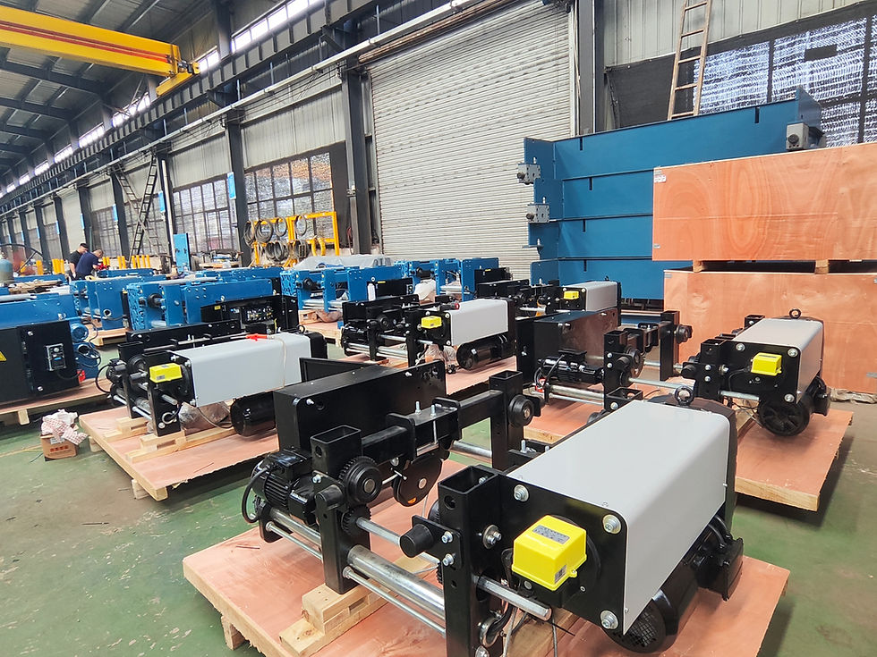
4. Structure of ladle crane
The ladle crane applies double-girder double-track and single trolley structure.
The ladle crane with double-girder double-track and single trolley is made up of electric control system, trolley, crane traveling mechanism, bridge and gantry hook. The main lifting and auxiliary lifting mechanism should be set on the same trolley. The trolley travels along the track of two main girders. The main hook, used to lift steel ladle or iron tank, is gantry spreader with two removable lamina hooks. The auxiliary hook is forged hook of laminated hook for pouring steel liquid or lifting other materials.

4.1. Trolley
Trolley consists of main lifting mechanism, auxiliary lifting mechanism, trolley traveling mechanism and trolley frame.
① Main Lifting mechanism
The main lifting system adopts double gear reducer and double drum block structure, which consists of two motors, two reducers, two drum block, four brakes and couplings.
The two reducers are driven by two motors to make the two drum block work. The two drum block which are in the output shaft of the reducer, are in the same axle and perpendicular to the main girder. The output shaft of the two reducers is connected by couplings to ensure the synchronization of the two drum block. Each reducer is equipped with two support brakes, whose safety factor is no less than 1.10. There are totally 4 support brakes in the hoisting mechanism. The wire rope on the two drum block, gantry hook, two fixed sheave groups and the balance beam form the four-wire rope reeving system. When one motor or one set of electric control device breaks down, another set of driving devices will ensure to finish a operation cycle with rated lifting capacity.
② auxiliary lifting mechanism
The auxiliary lifting mechanism adopts single reducer and single drum structure, which is made up of motor, reducer, drum block, brake and coupling.
The motor can drive the reducer to make the drum block work. Two support brakes are installed and the safety factor is not less than 1.25. Wire rope, hook group and fixed sheave group can form the wire rope reeving system.
③ trolley traveling mechanism
The trolley traveling mechanism adopts driving structure respectively, and consists of two sets of driving devices and wheel group. Main components of driving device include motors, brakes and reducers. Wheel group mainly contains driving wheel group and driven wheel group. Motor, reducer, brake and wheel devices are installed on the trolley frame. Motor, reducer and driving wheel group are connected by couplings. Two sets of wheel group are driven respectively by two driving devices.
④ trolley frame
The trolley frame is constructed by box-type beam and I beam with excellent strength and stiffness to ensure stable operation of hoisting mechanism and traveling mechanism.

4.2. gantry spreader
The gantry spreader is composed of fixed pulley block, cross beam, welded connecting piece, laminated hook, thermal insulation and so on.
4.3. Crane traveling mechanism
The crane traveling mechanism adopts separate driving structure with one drive at each corner, and consists of four sets of driving devices and wheel group. Main components of driving device include motors, brakes and reducers. Wheel device, that is bogie group, mainly contains driving wheel group and driven wheel group. Motor, reducer, and brake are installed in the main girder. Wheel devices are installed on the main girder. Motor, reducer and wheel devices are connected by universal couplings. Each driving device can drive a driving wheel group of one bogie group.

4.4. Bridge
Bridge is composed of main girder, end carriage and accessory structure. The construction of main girder and end carriage adopt welded box to ensure sufficient strength, stiffness and stability.
The main girder adopts the structure of bias-rail box-type, rail is installed on the T type steel of main web plate. Driving devices of crane traveling mechanism are installed on the two ends of the main girder. There should be a maintenance gate on the upper cover. The electrical room with heat insulating and sealing is equipped in the middle of one main girder and in which the electrical control components are installed. Electrical room is also equipped with industrial air cooler. There should be thermal baffle on the heating radiation surface of main girder.

4.5. Cabin
The cab adopts enclosed type with the function of thermal insulation. The upper front, sides of lower front and the back of the cab are all equipped with tempered glass. When sitting in the driver’s seat, the maximum elevation is 55~60°and the maximum depression 70~75°. When the operator is still, the maximum front view is 120°and the angle can increase to 270°when rotating the seat. The cab frame is constructed by rolled steel and pressing steel sheet with the cab floor covered by insulation rubber material.
4.6. Electric control system


Comments